

3 September 2026
By Graeme King
Boat maker Graeme King on how to design and build eight-oared shells.
In 1961 I was 14. On a Saturday morning after finishing adult woodworking classes a friend and I would spend an hour or two playing on the banks of the Torrens River that runs through Adelaide. It was there that I first came across what seemed to me to be a shiny and new wooden eight-oared rowing shell. After spending some time studying the construction and wondering how such a boat is made, I decided I would one day like to make one of these boats.
Eighteen years later, and after much experimenting as well as having considerable success designing and building singles, pairs, fours etc., I was given an order for an eight.
The following is how my thinking process evolved in designing eight-oared shells.
Apart from building a canoe and a couple of old-style surfboards before I was fifteen, I had no experience or formal training in boat building. In 1964 I started a five-year fitting and machining apprenticeship at the Islington Workshops where railroad locomotives, carriages, wagons etc. were designed and built. After three years of the metal working side of the apprenticeship, I was transferred to the design offices to gain experience in drafting and mechanical engineering where I did notice the only similarity between railroad rolling stock and rowing shells is they both had wheels that ran on rails.
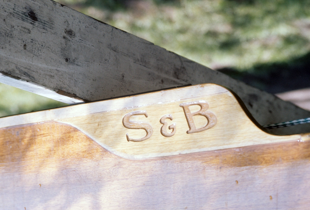
At the 1968 Olympics in Mexico City, Germany won the Eights race in a Karlisch beating the Australians who came second by about a third of a length and were using a Sargent & Burton (S&B) eight. I was familiar with the S&B eight and was able to see the Karlisch eight when it came to Australia after the Mexico Olympics. The S&B eight was longer with finer ends, but I felt the Karlisch eight was of a much lighter construction, including lighter fittings like the stretcher that just had shoes attached to a top bar and a keel plate to prevent the oarsmen feet from becoming too vertical.
The less than a second margin between the crews using these two reasonably different boat shapes left me thinking about hull shapes and how boat weight effects performance. So, in order to try and understand what is important, I decided to buy the book Basic Naval Architecture by K. Barnaby. This book together with a copy of the tank test results on three very different shaped eights done by J. Wellicome at the National Physical Laboratory in England plus about 1,600 photocopied pages from the Transactions of the Royal Institution of Naval Architects became my main reference source.
My thinking while designing that first eight was to make the hull as long as possible while keeping the wetted surface area to around 100 square feet. This meant going to a narrower and deeper hull which would lead to transverse stability problems or having finer ends and more volume or displacement towards the middle of the boat which would make the boat less longitudinally stable. The transverse stability problem with the narrower deeper hull could be reduced somewhat by setting the crew lower in the boat. The limitation here being how far down the oarsman’s feet could be placed.
All this was a bit of a balancing act, but what was a bit perplexing was what effect these compromises would have on wave drag. From what I was understanding at the time was, a longer, narrower and deeper hull would have less wave drag but by how much was the real question. It would be another seven years before I would better understand this problem.
This first eight I designed and built was launched at the Adelaide Rowing Club on Christmas Day 1979. This design would be the last wooden eights to be used at the IRA rowing championships in the USA, Harvard winning the championship in 1985 and Navy winning the championship in 1986. Although that would be the last time wooden eights would be raced by university crews, school crews would continue to race wooden eights, the last one built by me was for St. Paul’s School USA in 2003.
1987 a difficult year but a turning point
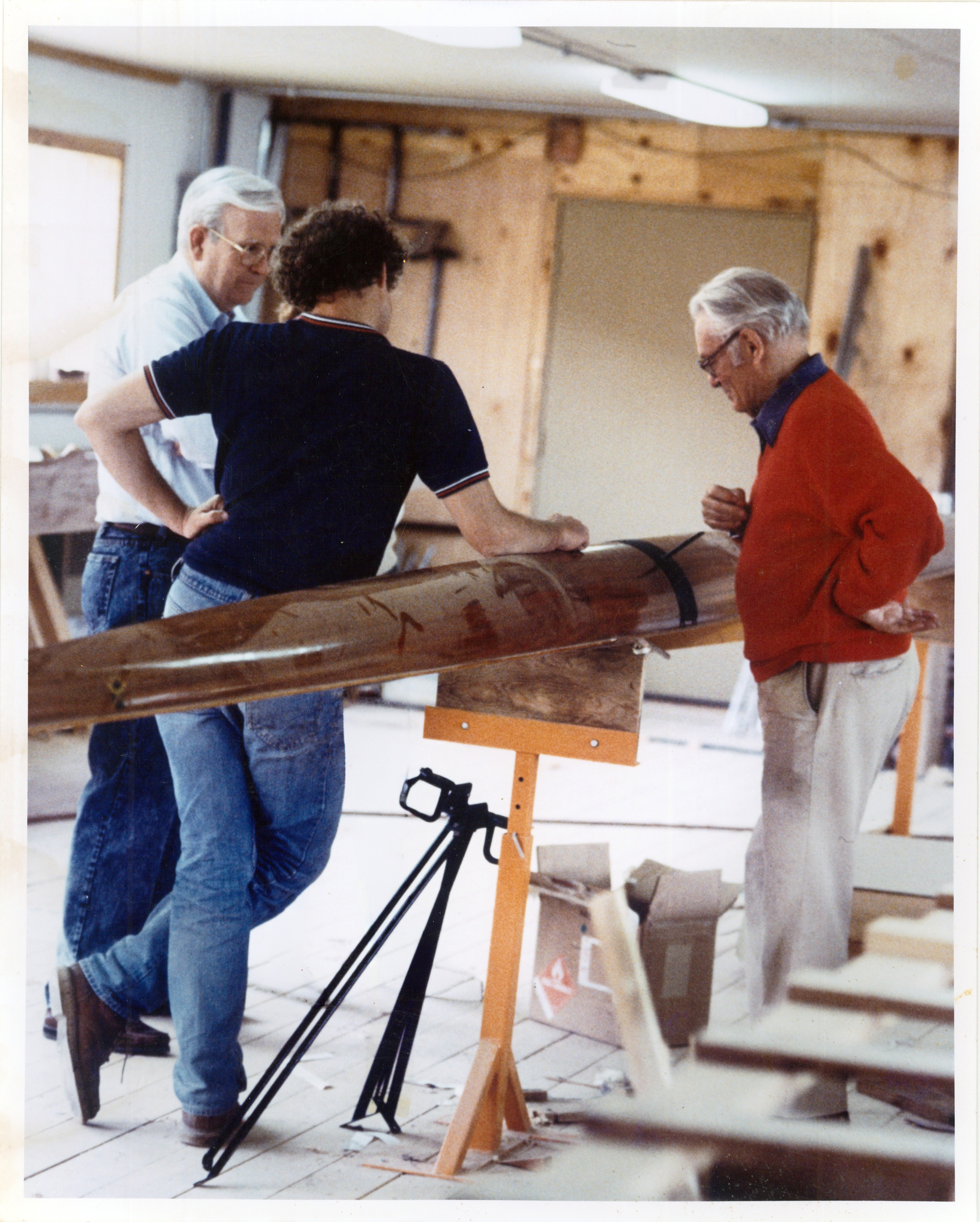
I was still building my Workshop during the winter of 1986/87 when St. Paul’s School wanted a new eight designed for their girls’ crew. Apart from the building not being fully enclosed and there being no heating, I had no plywood to make the boat. The plywood ordered from manufacturers proved to be most unsuitable. This forced me into making my own plywood and with that came a significant improvement in the quality of the boats.
In 1987 I built a boat for Bart Donahue, who had an interest in woodworking and was curious about rowing shell design, so naturally we developed a good friendship. I soon discovered he was the director of Bell Labs in the USA, and he offered any assistance I needed in further understanding of slender hull theory and trying to resolve the problem of wave drag.
That year I also moved to Putney in Vermont. I discovered that across the road from the house I was renting, lived the great American yacht designer, Olin Stephens. He became fascinated with the construction of the eights and other boats I was building, and he became very interested in the work Bart Donahue and I was doing on understanding the problem of wave drag.
With Olin Stephens bringing his yachting friends to the workshop, discussions would often turn to yacht designing, including the proposed AC designs for the America’s Cup, reinforcing my thoughts that both rowing shell designing and yacht designing require specialized knowledge.
The design problem
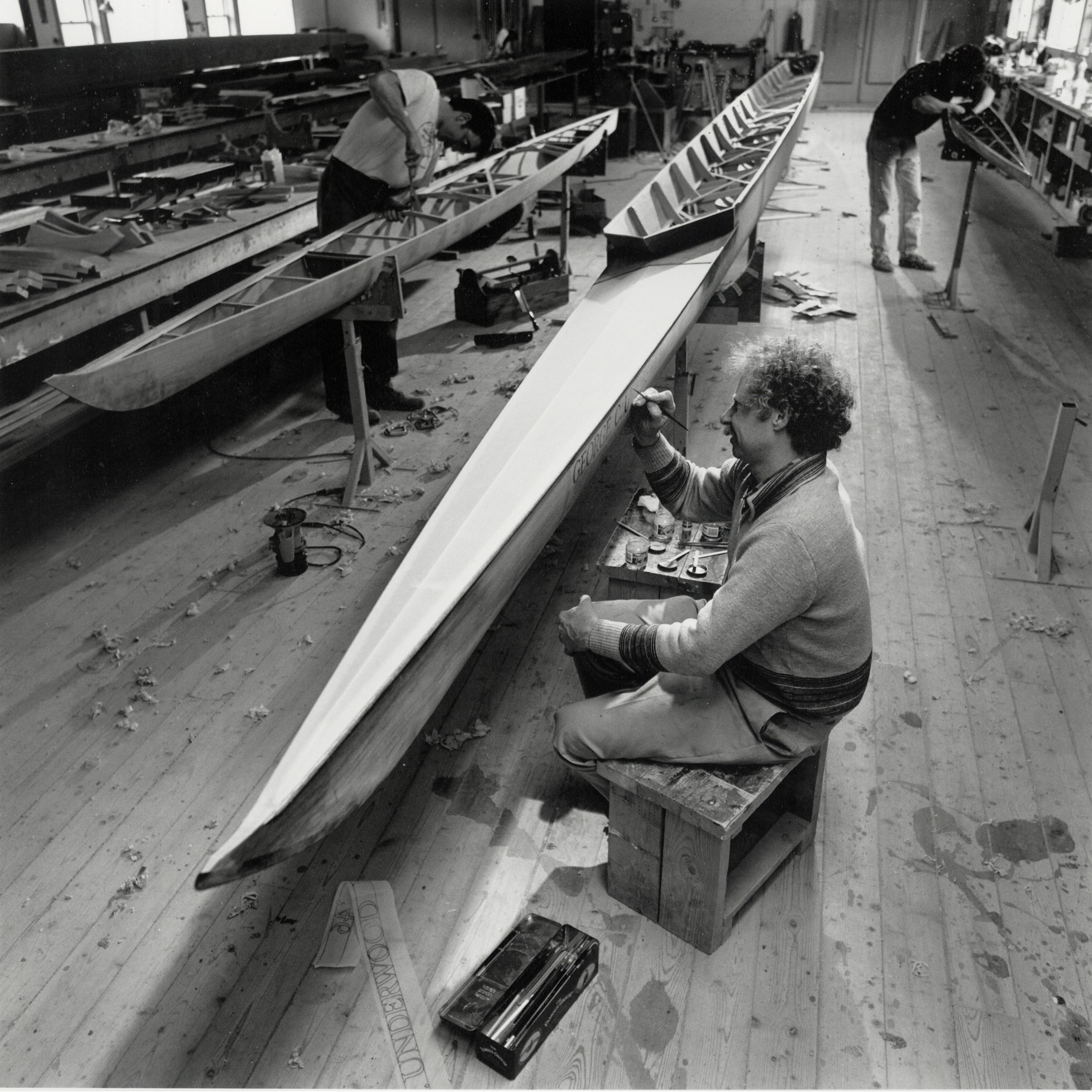
For a few years prior to 1987 I had been thinking about a narrower, deeper eight-oared shell with stabilizing fins. The reduction in wetted surface area could be easily calculated, and I knew a narrower deeper hull would reduce the wave drag but I had no idea by how much. Because of the prohibitive cost and what I considered the limitations of using scale models, I ruled out tank testing and thought more about mathematical modelling. For that I would need was a good mathematician rather than a naval architect.
Fortunately, Bart Donahue, of Bell Labs, was a mathematician and was most interested in the problem. Of the 1,600 photocopied pages from the Transactions of the Royal Institution of Naval Architects, I had sent him, he focused on work that had been first published in 1898 by an Australian mathematician, J. H. Mitchell. Although the actual paper in the Transactions of the Royal Institution of Naval Architects was presented a few years after that date. The complexity of the problem would require a computer that was not available in the 1890s.
A few years later, Olin Stephens and I went to hear a talk on slender hull theory being held at the Massachusetts Institute of Technology during which we were given a paper on J. H. Mitchell written by professor E. O. Tuck from Adelaide University who at the time along with L. Lazauskas were also dealing with slender hull theory.
The method
Bart Donahue developed a mathematical model, but it needed to be tested. The best way to do that was to scale up the body plans in the Wellicome report and compare mathematical modelling to the test tank results. [Editor’s remark: J.R. Wellicome performed physical resistance tests in a steady-speed rowing tank. The purpose was to evaluate hydrodynamic drag and aid the development of improved hull-form designs for rowing shells.]
When the Wellicome tests were done in 1967, a very fast eight would cover 2,000 metres usually between 6 min. 5 sec. and 6 min. 10 sec. Of the 56 test runs done in the rowing tank, only 9 were done at a speed that was within the current times for world championship crews of below 5 min. 30 sec. for 2,000 metres. At the lower speed range i.e. 5 min. 50 sec. to 6 min. for 2,000 metres, the Wellicome tank test results and Bart Donahue’s mathematical modelling for two of the boats were within ½% while for the third boat the variation was about 1 ½%. There was more of a scattering of results at higher speeds which was a bit of a puzzle, but we were generally happy with the results, plus it did give us a far better idea as to what to consider when dealing with wave drag and what to avoid.
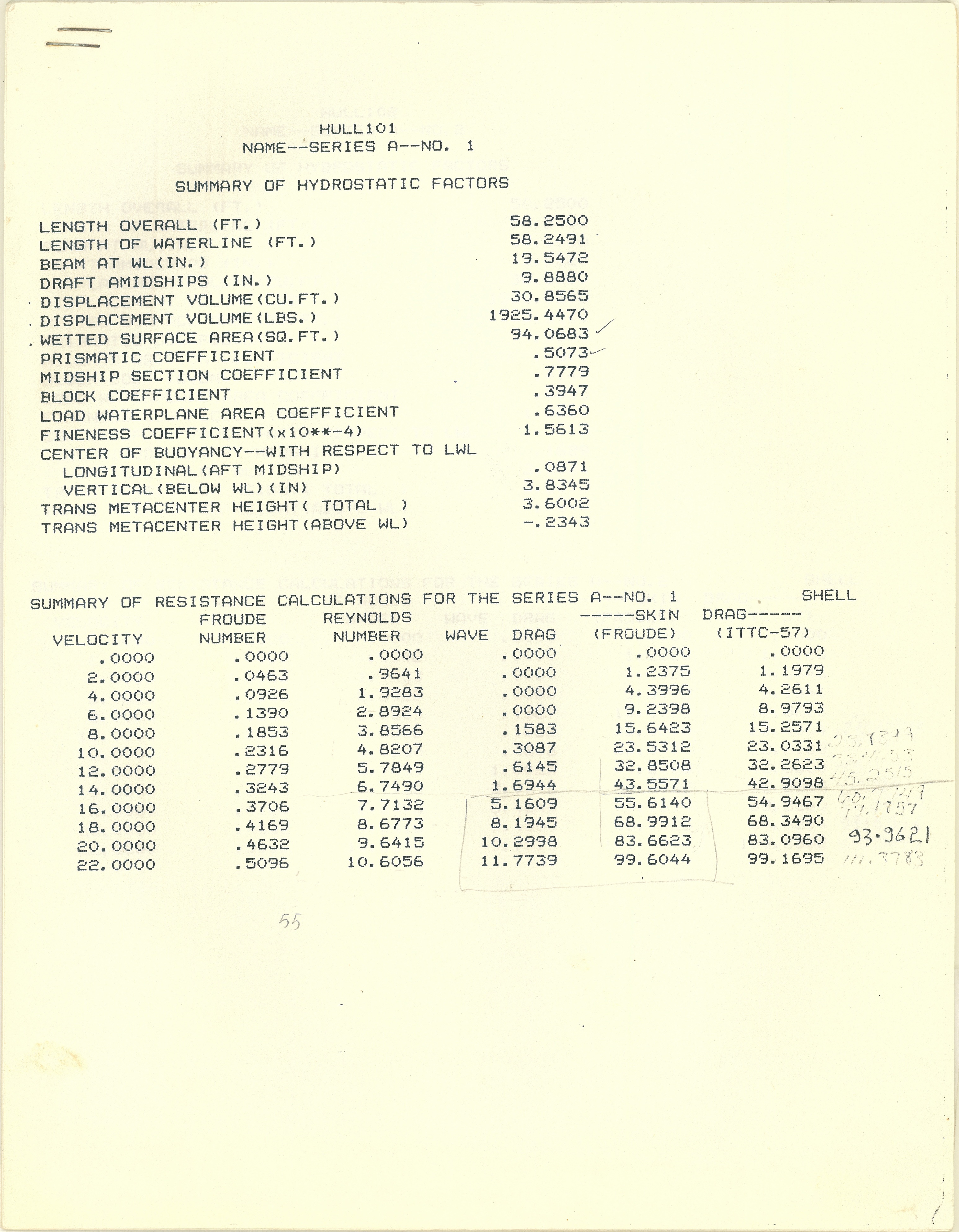
The next step was to draw up 6 displacement curves from which six 60-foot-long semicircular hulls with identical displacements could be developed. The results were plotted and from that the hull with the least total resistance was determined. After we considered the ideal displacement curve, the hull was lengthened or shortened to find an ideal length that would give the least total resistance then after that was determined, the sections were changed from semicircular to different beam/draught ratios. The last variable was to move the center of buoyancy forward or aft of mid ships to see how the total resistance would change.
The end result was a hull that would gain about 5 seconds over 2,000 metres, but a crew would not fit in the boat and if they did fit, it would be totally unrowable. Considerable knowledge and information were gained so that in moving forward, much of the guess work regarding wave drag was removed. All these calculations were done and used as a test on a new computer being developed at Bell Labs.
What we had determined as the optimum shape was gradually refined until a crew could fit in the boat while still giving about a 3% reduction in wetted surface area.
Ideally, deep narrow fins similar to those that had been tried on the single scull would be best, but due to the risk of damage, these were not practical, so a less efficient design was settled on. Because I wanted the fins placed where the turbulence of the boundary layer was still fairly thin as well as being placed in the area of the boat with maximum beam and also considering the pivoting point on the hull when the boat is turning, the fins were placed at a forty-five-degree angle from vertical or horizontal between the three and four seat. The fins also needed to be aligned with the flow of the water. To determine the flow direction, Harvard coach Harry Parker allowed a small hole to be drilled through the hull of one of Harvard’s boats into which a small tab fin was fitted to record the direction water flowed along the hull.
The downside to these boats was, besides damage to the fins, due to the boats needing speed for stability, they would be quite unstable when rowed on the paddle and when the boat did go off balance it would be more of a gentle roll and the same gentle row coming back to level. If a power boat went by the boat would do a quick double roll.
Although it would be totally impractical, it would be interesting to see what difference there would be in the boats’ stability if the deeper narrower fins were used.
The triple fin eight
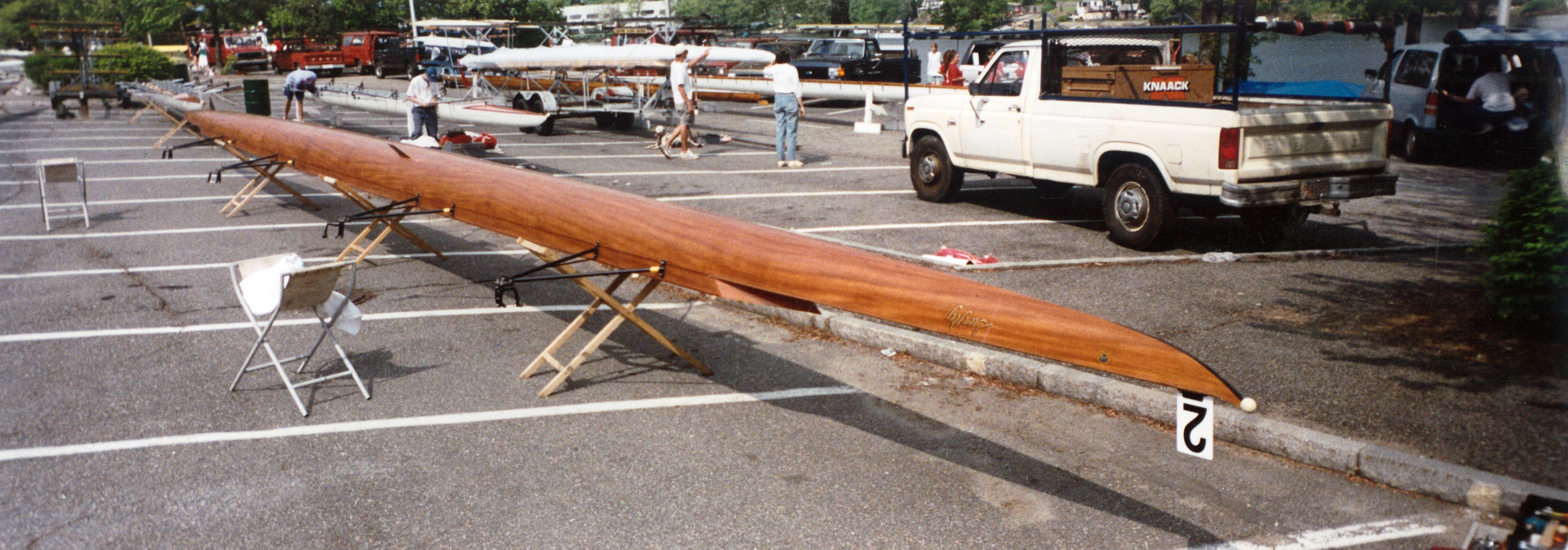
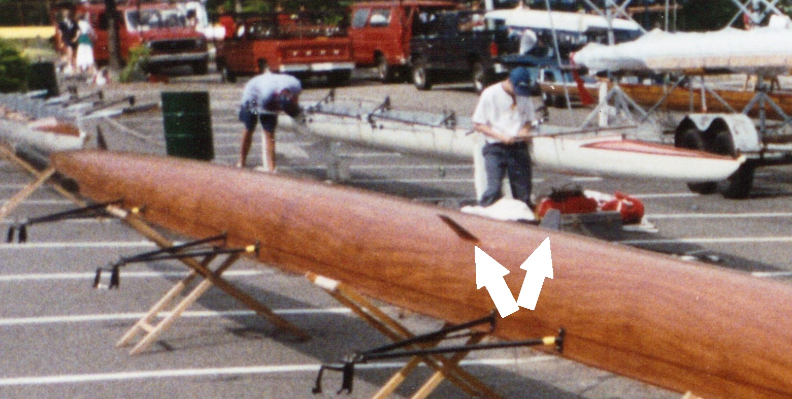
I had been getting positive stability results from strapping some extra fins on a single, so when the rowing coach at Phillips Exeter Academy asked me to build an eight, I asked if he would be willing to try an experimental design to which he agreed and was rewarded by the crew using the boat to win the school championship that year and set a new course record.
The most successful of these boats was one used by a St. Paul’s Crew (USA) delivered the following year, 1991. Of the thirteen championship races in which it was used, before being destroyed in a road accident, it recorded ten wins, two second places and one third place, including setting the course record at the NEIRA rowing championships that still stands in 2026.
The other unusual characteristic of these three fin wooden eights is they were very close to the FISA minimum weight requirements. In fact, one or two of the women’s eights being underweight were required to add weights when competing.
A replacement wooden eight-oared shell was built in 2003 for St. Paul’s School and with that boat, the chapter of me building wooden eights came to an end.
Quantum Racing
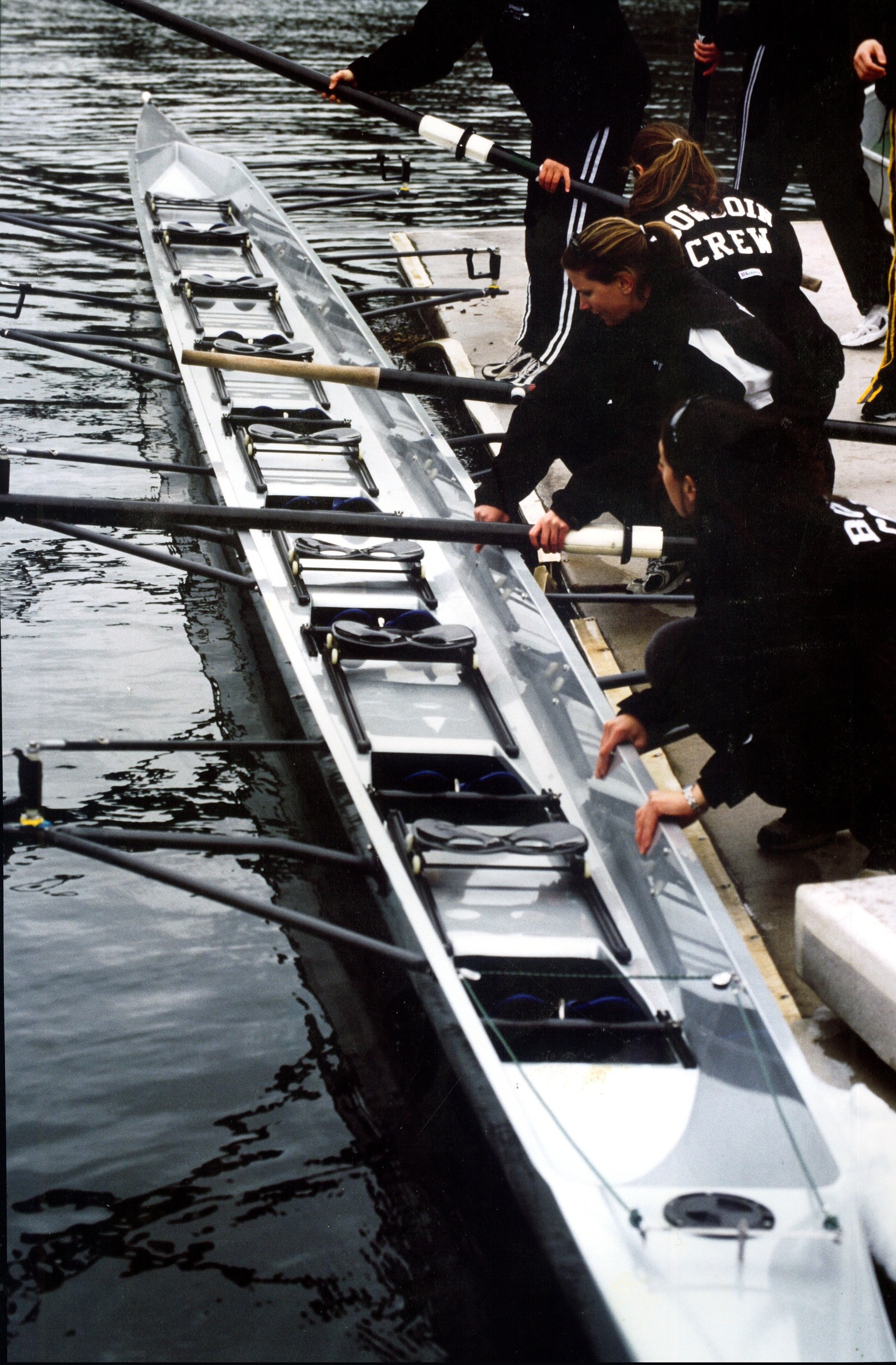
Quantum Racing was a boat building company that was founded in March of 2000 and lasted until around mid-2004.
In late 1998 I was asked if I would be interested in designing rowing shell hulls for a new boat building company. I would be given stocks in the company, paid royalties on boats produced and a consulting fee. Even though my workshop was a five-hour drive from the proposed facility, I agreed to what would become an unnecessary financial disaster.
The proposal was to build carbon fiber eights with carbon bow mounted wing riggers. However, I managed to convince the company managers to first try their unproven ideas out on a single scull. I would supply the lines for the boat that was first launched at the end of October 2000. The single hull shape was so drastically changed and cut down that at the catch, the stern deck was at water level and at the finish of the rowing stroke, due to the low deck profile and a rounded bow creating an unusual wake, the bow number clip was in the water.
There were serious problems with the mounting system for the bow mounted wing rigger and despite the boat being heavy, the decks under load soon began to buckle. It was then decided that the people responsible for the unsatisfactory single could work on rectifying all the problems while I worked on designing an eight.
The three fin eight design was not practical so that left a choice between side mounted riggers and wing riggers. Considering the likely delays in developing the carbon wing rigger, it would be easier to cut down a boat mold rather than adding height. This together with my thinking that a boat with side mounted riggers would be more comfortable to row, I settled on designing a new conventional hull with side mounted riggers.
Besides doing the calculations and developing lines for the eight, I now found myself very much involved with the selection of materials for laminating the hull as well as the lay-up of the materials and later taking over the interior design.
The first eight produced had a very positive test row in April 2001 and the following week the single project was shelved so those involved in that project could focus on building eights.
Crews liked the boats, and they were having successes racing but workmanship and reliability remained a problem.
Compounding the problems and despite me in December the previous year warning about the danger of the oven catching fire, it did suspiciously catch fire during a night in August, resulting in much of the building being damaged with molds, boats, equipment and materials being destroyed.
Despite the setback plans for the midweight eight and four were finished by the beginning of November 2001 and the boats on the water in March 2002.
A lightweight and a midweight eight and midweight four would be the only boats designed for Quantum Racing, and in June 2004 rumors started that workers from Quantum were in China to teach the Chinese how to build high temperature cured carbon fiber rowing shells for a new company that would be known as WinTech.
WinTech and King Racing

When the WinTech eights arrived in the USA, they were not well received and sales were disappointing. In 2009 the US WinTech manager asked if I would be interested in designing wing rigger eights for WinTech.
Having in the past been the Harvard boatman looking after about 30 eights, my thinking now was to design an eight where a port and a starboard rigger would fit any position in the boat thus reducing the number of spare parts required. There was considerable resistance to this idea because it was considered impossible without compromising the shape of the hull below the waterline.
However, the idea was finally accepted after a rather large model of the hull was produced using the below waterline hull shape designed for the Quantum boat company but adding considerable flare above the waterline. At the same time, I also started thinking about four sizes of eights where the two smaller boats could use the same port and starboard riggers and the two larger boats would use the same port and starboard riggers.
Oddly enough, lessons from building two versions of the triple fin eights made me think this idea was possible and that had to do with the difference in the flair in the hull of the two triple fin boats. The more vertical the sides, the stiffer the boat so in the middle of the boat the sides close to vertical as possible and gradually add flair going towards the ends where stresses are reduced and where the flair is needed. With that said, I have had very little input into the structural engineering of the boats, but I did insist on having final say on the placement of the crew.
Since the introduction of the first of these boats in 2011 and the last in 2024, crews using them have won numerous races at Head of the Charles as well as holding several of the course records. They are regarded as comfortable to row and maintain speed while easily steering the winding Head of the Charles course.
To a casual observer watching a good crew makes rowing look so easy; and just like rowing, designing eights seems so easy, but it is full of pitfalls and the chances of designing something that is not an improvement is far greater than creating an improved design. Also, like rowing itself, I very much think the best results come from the meshing of science and art. People claim boats are 5 seconds faster and for that to happen there would need to be a dramatic change in design i.e. using foils if it was practical or reducing the wetted surface area by almost 3 square feet.
An example, the actual resistance curve taken from a typical eight with 100 square feet of wetted surface area, at 5 minutes 45 seconds for 2,000 metres has a total resistance of 88.5 pounds with 82.25 pounds being skin friction but to clock 5 minutes 40 seconds the total resistance will be 91.2 pounds with 84.65 pounds being skin friction therefore the reduction in wetted surface area would need to be 100 – (100x 82.25/84.65) = 2.84 square feet which brings us back close to the wetted surface area of the triple fin eight discussed earlier.
My thinking at that moment is, because of the conditions in which the eights are used, they are, if not now, close to their most efficient shape and any difference in performance lies in the crew’s comfort.
For me, considering the high cost of making the plugs and molds there was considerable pressure to get the design right and considering my age it is probably best I don’t try to design another racing shell.
But if I did…
The quad scull probably has the most potential for an improvement in both hull design and layout, but one would need to study existing hull lines to see if any meaningful improvement can be made. For overall crew comfort, I would be inclined to use side mounted riggers even though they are not as convenient to make by the manufacturer or as convenient to use.
More on wing riggers and side mounted riggers later and that flows into the sometimes-misguided importance of boat weight.
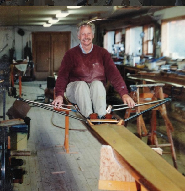


Graeme and I came to Newell Boathouse near the same time — and I delighted in our friendship which first grew during the 1973 spring and summer as I tried to make the National Teams boats. His dry and delightful humor is evident in this detailed review of his journey as a sculler, rower, designer and thinker. Well rowed and told, Graeme.